Bringing An Old Hardinge HC (Chucker) Back To Life
Copyright 2010 by James P. Riser
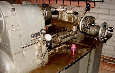

I decided to buy and bring this old lathe back to life
to manufacture two items that I have held off on due to lack of
the proper machine for the job. After some extensive remodeling,
this old chucker will do the jobs nicely.
When I bought the lathe, I was informed that it did
run - several years ago and that the power feed motor was burnt
out. I decided to take a chance on it. The machine had sit around
for a number of years and was rather dirty.
The lathe was loaded onto my trailer for the ride home.


Removing heavy machines from my trailer is always a
fun activity - one done slowly and carefully. I use my engine
hoist and steel cables.
Notice that the lathe is supported by steel bars under
the ends of the chip tray - not by the headstock nor bed.

 I slowly lowered the lathe on to the legs of the hoist
to support it while I drilled the steel base to accept axles for
moving the machine.
I slowly lowered the lathe on to the legs of the hoist
to support it while I drilled the steel base to accept axles for
moving the machine.
 Here are the wheels temporarily mounted on the machine.

The lathe came with the tooling shown below. All I
will require will be an assortment of Hardinge HC tool holders.


 Here is the limited
turret tooling that came with the lathe. This is an 8 position
turret.
Here is the limited
turret tooling that came with the lathe. This is an 8 position
turret.
A very different speed adjustment ...
This plate is on the inside of the motor compartment
door. Two cams needed to be set and locked in position to adjust
speed ranges. By shifting a lever topside, the three speed ranges
would be changed as programmed by the cams.
 These are the two adjustment cams with the locking
ring on the left.
These are the two adjustment cams with the locking
ring on the left. 
 Disassembly has
started.
Disassembly has
started.
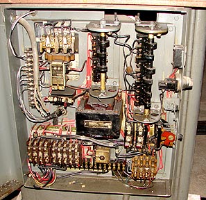 This is the wiring setup for the
lathe. Speed control wires had been disconnected.
The rear of the speed control looked like this.
This is the wiring setup for the
lathe. Speed control wires had been disconnected.
The rear of the speed control looked like this. 
 Here is another
view. Notice that the belt is missing teeth!
I decided to bypass all of the electrics and hook up
a new VFD directly to the high speed side of the motor windings.
Here is another
view. Notice that the belt is missing teeth!
I decided to bypass all of the electrics and hook up
a new VFD directly to the high speed side of the motor windings.

 On the left is testing for motor rotation direction.
On the right is the completed wiring through
the side of the electrical box.
I utilized some now unused terminal strip
for connecting the VFD wires.
On the left is testing for motor rotation direction.
On the right is the completed wiring through
the side of the electrical box.
I utilized some now unused terminal strip
for connecting the VFD wires.
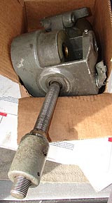
 Here is the disassembled and removed speed control
with its motor.
It turns out that the motor windings are burnt out
- probably why all of the wires had been disconnected.
I'll replace this unit as stripped down
to control the variable speed belt mechanism.
This is what the speed control will look like. Since
with the VFD I will very seldom change belt ratios, I have decided
to make it all manual for the adjustment. A pulley has been installed
to serve as a temporary handwheel for testing. This will work
fine for the limited adjusting I will require on the projects
in mind for this lathe.
Here is the disassembled and removed speed control
with its motor.
It turns out that the motor windings are burnt out
- probably why all of the wires had been disconnected.
I'll replace this unit as stripped down
to control the variable speed belt mechanism.
This is what the speed control will look like. Since
with the VFD I will very seldom change belt ratios, I have decided
to make it all manual for the adjustment. A pulley has been installed
to serve as a temporary handwheel for testing. This will work
fine for the limited adjusting I will require on the projects
in mind for this lathe.


 As you can see, the burnt out motor, the cam system,
and all unneeded parts have been removed.
Here is the lathe with the variable pulley unit just
tied in the high speed position.
As you can see, the burnt out motor, the cam system,
and all unneeded parts have been removed.
Here is the lathe with the variable pulley unit just
tied in the high speed position. 
 Here is the speed
adjustment with the new belts. All works fine.
Here is the speed
adjustment with the new belts. All works fine. 
 A previous owner
added a block of nylon.
A previous owner
added a block of nylon.  This nylon block was added to hold the pulley in position.
Adjusting the motor mounts should fix the drifting pulley problem.
In preparation for the new belt set, the old ones are
removed. The secondary belt comes out throught the end of the
headstock.
This nylon block was added to hold the pulley in position.
Adjusting the motor mounts should fix the drifting pulley problem.
In preparation for the new belt set, the old ones are
removed. The secondary belt comes out throught the end of the
headstock.


 This is the VFD I used.
 It is mounted as so.
  With this VFD unit I can adjust the lathe from just
ticking over for threading operations to 3000 rpm for finishing
work. Nice!
With this VFD unit I can adjust the lathe from just
ticking over for threading operations to 3000 rpm for finishing
work. Nice!
 I was able to get
the power feed working again.
The coolant sump was cleaned and will get drain plumbing
installed.
I was able to get
the power feed working again.
The coolant sump was cleaned and will get drain plumbing
installed. 
 I cleaned the coolant
pump. It works and will get remounted with the screen filter.
The coolant pump has been rewired and remounted. Here
is the new drain line with valve for the coolant sump.
I cleaned the coolant
pump. It works and will get remounted with the screen filter.
The coolant pump has been rewired and remounted. Here
is the new drain line with valve for the coolant sump.


 The belts were in horrible shape and new ones have
been installed.
Here are the turret tool holders. Since any one setup
might require duplicate types of holders, you will see multiples
of useful holders.
The belts were in horrible shape and new ones have
been installed.
Here are the turret tool holders. Since any one setup
might require duplicate types of holders, you will see multiples
of useful holders.
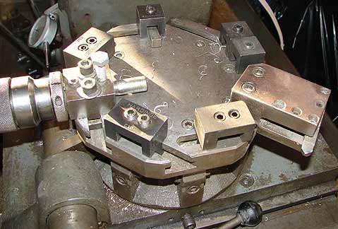 This is an assortment
mounted on the turret.
This is an assortment
mounted on the turret.

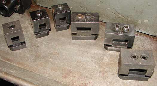 These hold 1 or
2 (3/8") lathe tools.
Here you can see the bottom of a 5/8" holder and
a single tool holder.
These hold 1 or
2 (3/8") lathe tools.
Here you can see the bottom of a 5/8" holder and
a single tool holder. 
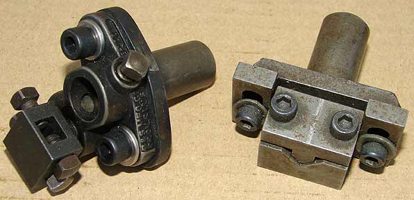
 This is how the
5/8" holders hook over the turret edge for accuracy.
The two set screws hold separate lathe tools for multiple
cuts.
This is how the
5/8" holders hook over the turret edge for accuracy.
The two set screws hold separate lathe tools for multiple
cuts. 


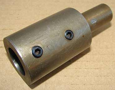
 This offset holder
allows machining from the side.
There is no point in having a lathe like this without
proper tooling. Here is a selection that I have available for
making my products. These all plug into the turret tool holders.
This offset holder
allows machining from the side.
There is no point in having a lathe like this without
proper tooling. Here is a selection that I have available for
making my products. These all plug into the turret tool holders.


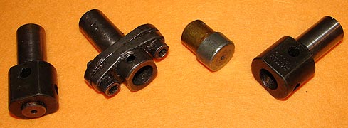


 I can use the same
tooling on my other turret lathe with bushings.
I just had to do a quick and dirty facing cut on the
end of some aluminum scrap to test the lathe. The old Hardinge
Chucker is now ready to earn its keep.
I can use the same
tooling on my other turret lathe with bushings.
I just had to do a quick and dirty facing cut on the
end of some aluminum scrap to test the lathe. The old Hardinge
Chucker is now ready to earn its keep.
 This is the "as
cut" finish on a 3" disc of aluminum.
This is the "as
cut" finish on a 3" disc of aluminum. The above was cut with no radius on the tool. Below
is with a slight radius.
The above was cut with no radius on the tool. Below
is with a slight radius.

 And after 20 seconds
with Nevr-Dull.
And after 20 seconds
with Nevr-Dull.  Once the lathe was up and earning money, I decided
to add a small steel storage box for the assorted tooling.
I picked up a used electrical box from a demolition
company to modify as the box. It had the usual pivoting cover.
Using my HF spot welder, I made the required changes
to the box.
Once the lathe was up and earning money, I decided
to add a small steel storage box for the assorted tooling.
I picked up a used electrical box from a demolition
company to modify as the box. It had the usual pivoting cover.
Using my HF spot welder, I made the required changes
to the box.


 After spot welding on hinges, hasp, and staple (plus
some mods to the box), I bolted it to the end of the lathe base.
BTW - the welder worked great.
After spot welding on hinges, hasp, and staple (plus
some mods to the box), I bolted it to the end of the lathe base.
BTW - the welder worked great.
 Here
it is before priming/painting.
Shelving strips were mounted inside.
Here
it is before priming/painting.
Shelving strips were mounted inside. 
 The shelves were
two pieces of metal bent to hook over the supports.
The turret tooling was placed inside for safe storage.
The shelves were
two pieces of metal bent to hook over the supports.
The turret tooling was placed inside for safe storage.

 Here is the completed
box after painting.
Everything is lockable.
Here is the completed
box after painting.
Everything is lockable.  This is all of the "fixing" that I will do
to this old HC.
This is all of the "fixing" that I will do
to this old HC.