A Homemade Rotary Broach
(Idea from randyc on the Practical Machinist Forum)
Photos and text copyright 2014 by James P. Riser
For an upcoming project I need to have square holes.
On the prototype I merely filed a round hole to shape. This will
not do for production. I was very pleased to see a thread by randyc
on the Practical Machinist Forum. His design for a rotary broach
would work for my upcoming needs. This is my build of his design.
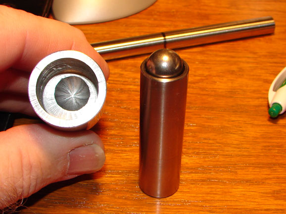 The machined parts
for the rotary broaching tool are shown here. This is standard
machining.
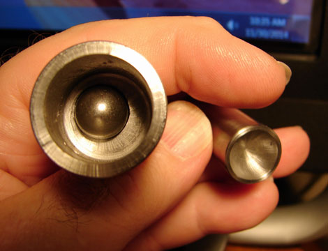 Here is the ball
bearing in position between the parts.
 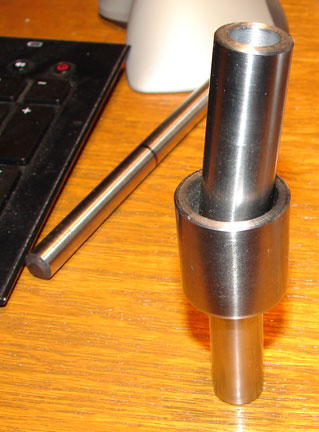 On the left is the body of the holder with its offset
depression. The piece on the right has a matching depression in
one end. The other end was drilled and bored to hold the 10mm
broaching tool.
A groove is needed in the bearing end of this holder.
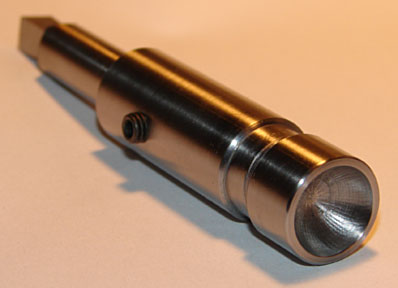 The assembled parts are shown here.
 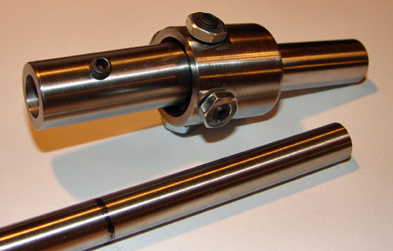 The holder was made from available tool steel pieces
in my "scrap bin". The body is 1" diameter A-2
with one end turned down to 1/2" and the tool holder is 5/8"
diameter W-1. The broach tool is made from 10mm HSS drill blank.
This came in a 5" length and needed to be cut in half.
As with the original described on the Practical Machinist
Forum, the 4 set screws merely keep the holder from falling apart.
The set screws extend into the groove turned into the holder but
do not clamp down on the holder. Wheel bearing grease lubes the
ball bearing. (See full description of the construction in the
thread by randyc).
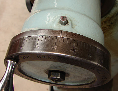
The drill blank was ground to the required shape on
my old Gorton 375 grinder. The angle on the grinder was set to
2 degrees for clearance on the cutter as it broached the square
hole. My plan was to have the tool angle greater than the usual
1 degree angle usually utilized on such tooling. I figured this
would give me the "action" I desired.
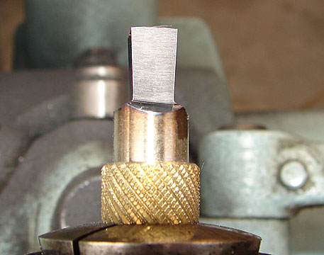
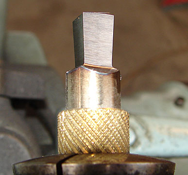
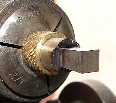
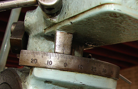 The grinding - start to finish (the brass is a bushing
I made to hold 10mm rod in a 1/2" collet):
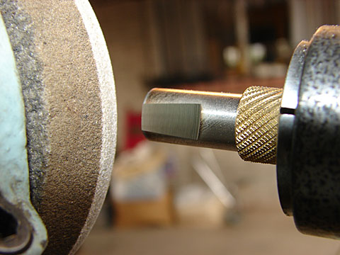
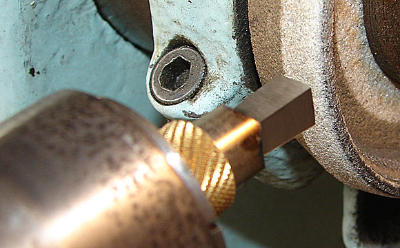 The depth of the grind was controlled so that all four
faces of the cutter matched.
 I decided to try something new on the end or tip grind.
Most sources suggest a concave end, randyc indicated that a flat
grind will remain sharp longer than concave. I adjusted the tool
to be centered on the grinding wheel to grind a curved tip. The
theory being that it would be a compromise between a concave and
flat grind with all 4 corners being sharp. The approach angle
was set to 0 degrees for this grind.

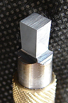
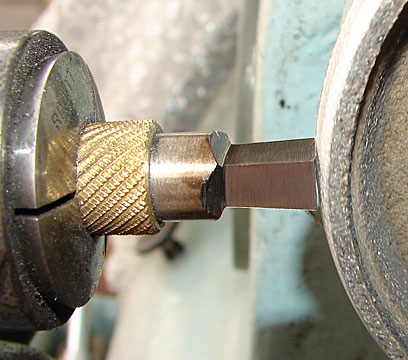 The final tip grind matches the curvature of the grinding
wheel.
A close up of the cutting tip:
 The whole project was now ready for testing on a scrap
piece of aluminum. The test was done on my old drill press at
slowest speed.
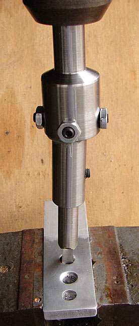 Notice the three holes. The one at the bottom is just
a 1/4" hole.
A countersink was used on the other two holes.
The tool tip was pressed into the countersunk depression
to center it then the drill press turned on.
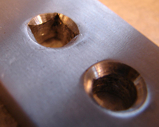
The tool quietly broached its way through the aluminum
as hoped.
Here is the result of my first trial - it worked beautifully!
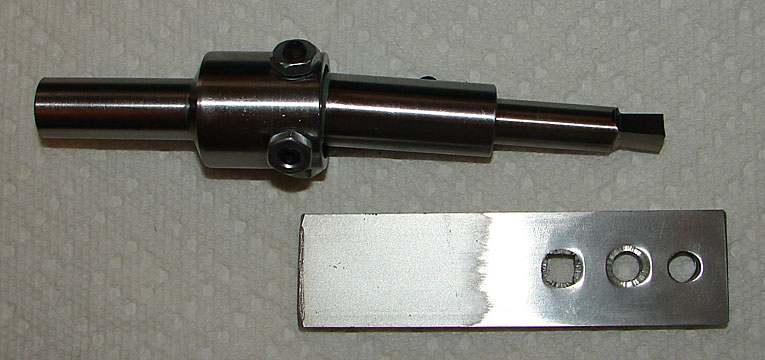
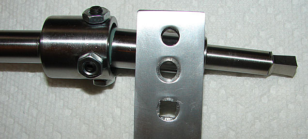 My sincere thanks to randyc for the design!
 The machined parts
for the rotary broaching tool are shown here. This is standard
machining.
 The machined parts
for the rotary broaching tool are shown here. This is standard
machining.
 Here is the ball
bearing in position between the parts.


