A1 - Making the Barrel

Copyright 2011 by James P. Riser
On this page I shall document how I am making the barrel
for five items. Some of the methods of construction will differ
from standard clock construction. The items that I am making will
not be running 24 hours a day for hundreds of years so I am deviating
from standard designs which are necessary for clocks. These items
are not clocks and will only be run for seconds at a time perhaps
only a few times per year. Those familiar with clock building,
will see where I veer from the norm.
The first deviation from the norm ... I make the barrel
hooks or anchors from steel nail heads. I have found the steel
perfect for this purpose.
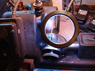 I am using my Gorton
265 bench top tool grinder for this task.
The angle is set to "0" degrees.
I am using my Gorton
265 bench top tool grinder for this task.
The angle is set to "0" degrees. 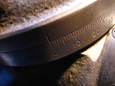
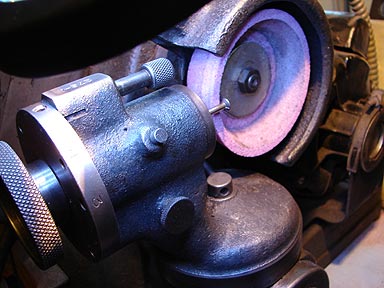 The nail is mounted
in the correct size of collet and grinding begins.
The nail is mounted
in the correct size of collet and grinding begins.
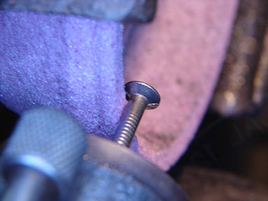 The shank is ground
true.
The shank is ground
true. 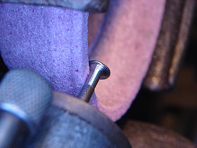
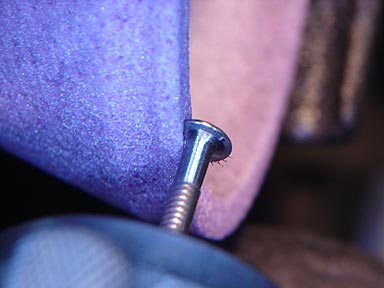 And two sides ground
down.
And two sides ground
down. 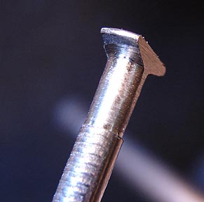 Cleaned up the barrel hooks to be look like this.
 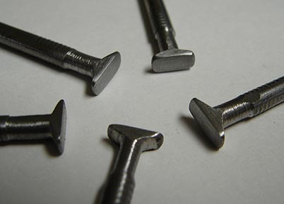 These hooks will be cut off from the nail body shortly.
The second deviation from the norm is that these hooks will work
no matter which direction the spring is wound. This makes design
changes down the road much easier if I choose to reverse the direction
of motion.
These hooks will be cut off from the nail body shortly.
The second deviation from the norm is that these hooks will work
no matter which direction the spring is wound. This makes design
changes down the road much easier if I choose to reverse the direction
of motion.
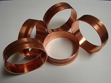
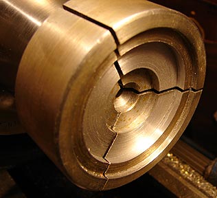
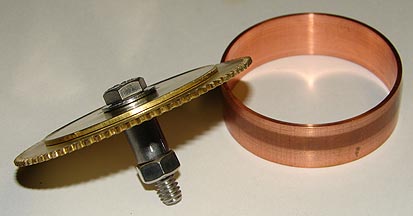
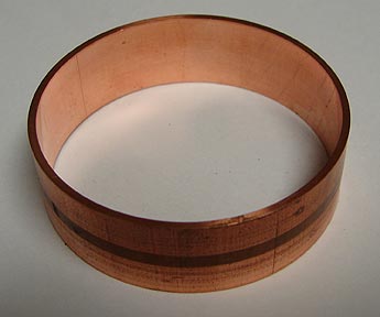 To keep the works visually appealing
and interesting, I will be
using heavy copper for the barrel bodies.
This is a rough idea of how things will look after
a bit more work.
To keep the works visually appealing
and interesting, I will be
using heavy copper for the barrel bodies.
This is a rough idea of how things will look after
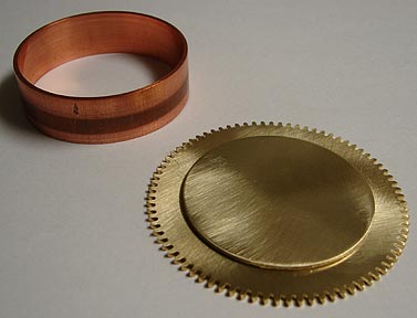
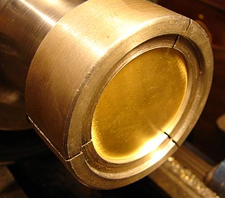
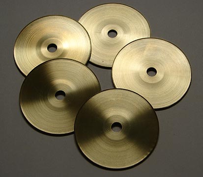
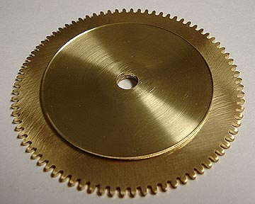
a bit more work. 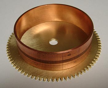 2" discs of brass were punched out as part of
the barrel assembly.
2" discs of brass were punched out as part of
the barrel assembly.
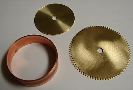
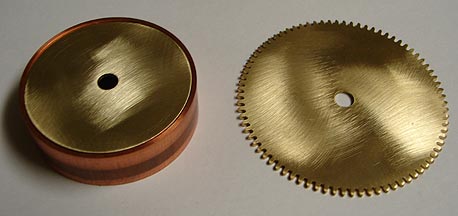
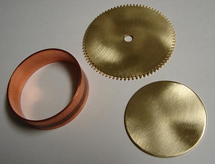 These are the parts
made up until now.
The brass disc just fits into the copper ring.
These are the parts
made up until now.
The brass disc just fits into the copper ring. 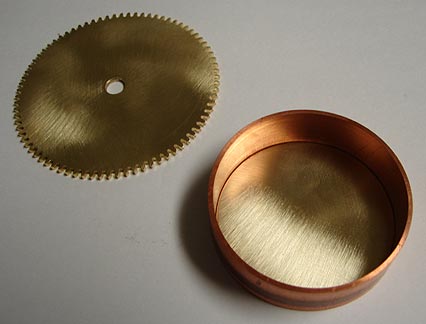
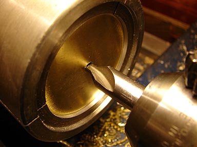
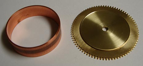
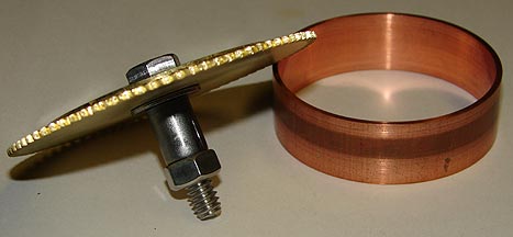
 After center drilling
with a hole to match the gear hole, the disc will go here.
All parts will be aligned and soldered in this position
to make the barrel body.
After center drilling
with a hole to match the gear hole, the disc will go here.
All parts will be aligned and soldered in this position
to make the barrel body. 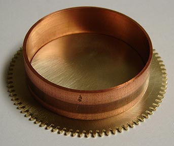 In order to get the disc ready for soldering a pot
chuck must be modified to securely hold the disc.
In order to get the disc ready for soldering a pot
chuck must be modified to securely hold the disc.
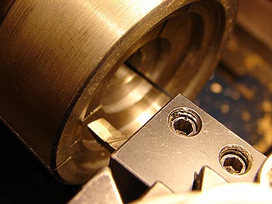
 The center hole is be carefully drilled.
 The disc hole is carefully drilled to final size.
 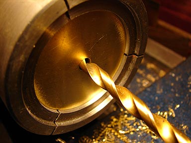 The resulting hole is just fine for my needs with no
measurable loss of concentricity.
The disc is then machined to leave the center high
and a slight edge rim.
The resulting hole is just fine for my needs with no
measurable loss of concentricity.
The disc is then machined to leave the center high
and a slight edge rim. 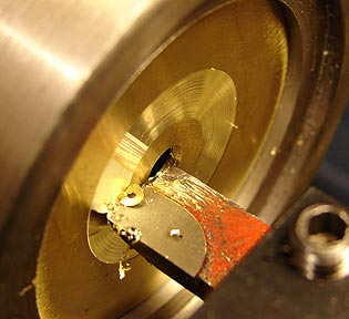
 This raised center
will help to reduce friction when in operation.
The parts now look like this. The slight edge rim provides
increased surface area for soldering.
This raised center
will help to reduce friction when in operation.
The parts now look like this. The slight edge rim provides
increased surface area for soldering.
 The disc hole lines up with the barrel wheel hole.
This disc just fits inside the barrel body.
The disc hole lines up with the barrel wheel hole.
This disc just fits inside the barrel body.
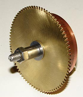
 Assembled, the parts look like this.
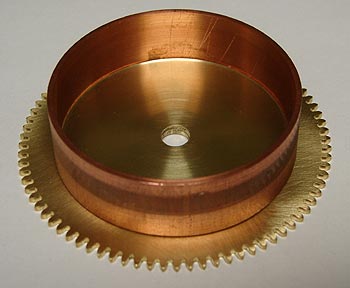
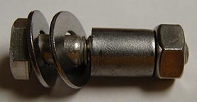 A stainless steel
bolt, two washers, a steel spacer, and a nut will hold the parts
for soldering.
This is how the parts are secured for soldering.
A stainless steel
bolt, two washers, a steel spacer, and a nut will hold the parts
for soldering.
This is how the parts are secured for soldering.
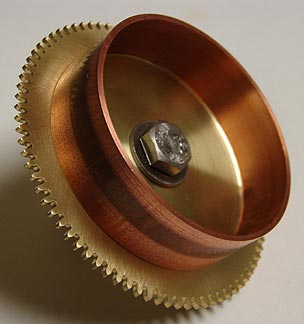
 Once the disc and barrel wheel are bolted together,
the barrel body is fitted over the disc. This is a test fit of
the parts.
Once the disc and barrel wheel are bolted together,
the barrel body is fitted over the disc. This is a test fit of
the parts.
 The next step with the barrel will the installation
of the barrel anchor or hook. This will be followed by soldering
everything together.
Before I finish the barrels, I am going to start on
what I call the brake wheel. That info is on page 4.
Click here to go to page 2
Click here to go to page 4
The next step with the barrel will the installation
of the barrel anchor or hook. This will be followed by soldering
everything together.
Before I finish the barrels, I am going to start on
what I call the brake wheel. That info is on page 4.
Click here to go to page 2
Click here to go to page 4